IM4000 Step-by-Step Assembly Instructions
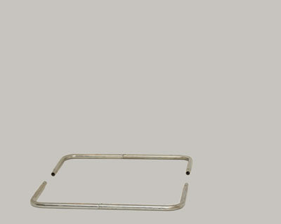
Remove the four L-shaped frame pieces (CC & DD) and join the CC pieces to the DD pieces. Be sure the two open ends match each other in height. The width of the frame should be approximately 28”. If the frame is narrower than 28" check the position of the pieces. You must have the LONG side of each L-shape on the ground.

Find the two V-shaped pieces (BB) and connect to the open ends on one side and then the other. Secure each piece with the screws & nuts supplied.
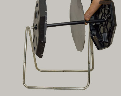
Find the horizontal axle bar (AA) and then the black plastic sleeve (FF). Slide the sleeve over the bar. Add the two end caps (part-A) and the center divider wall (F) onto the axle. Join the axle to the stand with the two long screws & nuts.

The part-A end cap pieces have different numbers of holes along each lip. Locate the lip that has 7 holes instead of 4. (There is a center hole in this lip.) Rotate this lip to the top so that it is facing UP on both end caps.
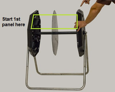
Keep the two end caps in position from the previous step. You MUST ensure that the lip with 7 holes remains facing UP on BOTH part-A end cap pieces before you add the first panel.
Place your first side panel on the first plane down from the top.
Fit the side panel in place and line-up the 4 holes. Be sure to fit the center divider into the slot on the underside of the panel and secure with small screws and nuts.

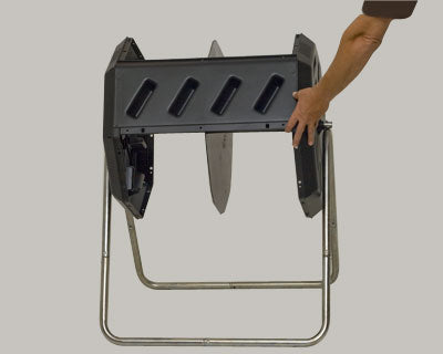
Rotate the unit and repeat the previous step for the remaining part-B body panels.

The door (C & D) must be the last panel added. (Part-C is the frame panel that is screwed to the body, part-D is the sliding door piece; both are assembled together at the factory.) The C piece must be added to the lip with 7 holes that was at the top when you began assembly.
If you have reached a point in your assembly where the pins no longer align with the holes then BOTH of your part-A end pieces were not facing UP in the correct orientation when you began assembly. They are probably twisted slightly in relation to one another and now since the part-B and part-C pieces have different pins they will not align correctly with the part-A end piece. The only solution is to remove all the panels and start again.